Pool House: A Study in Detail & Structural Development
by Mark English, AIA | Work/News
We use digital modeling programs, hand sketches and CAD drawings to investigate and finalize all of the key connections, in support of the design idea.
The drawings shown here document how we investigate and study details in architecture.
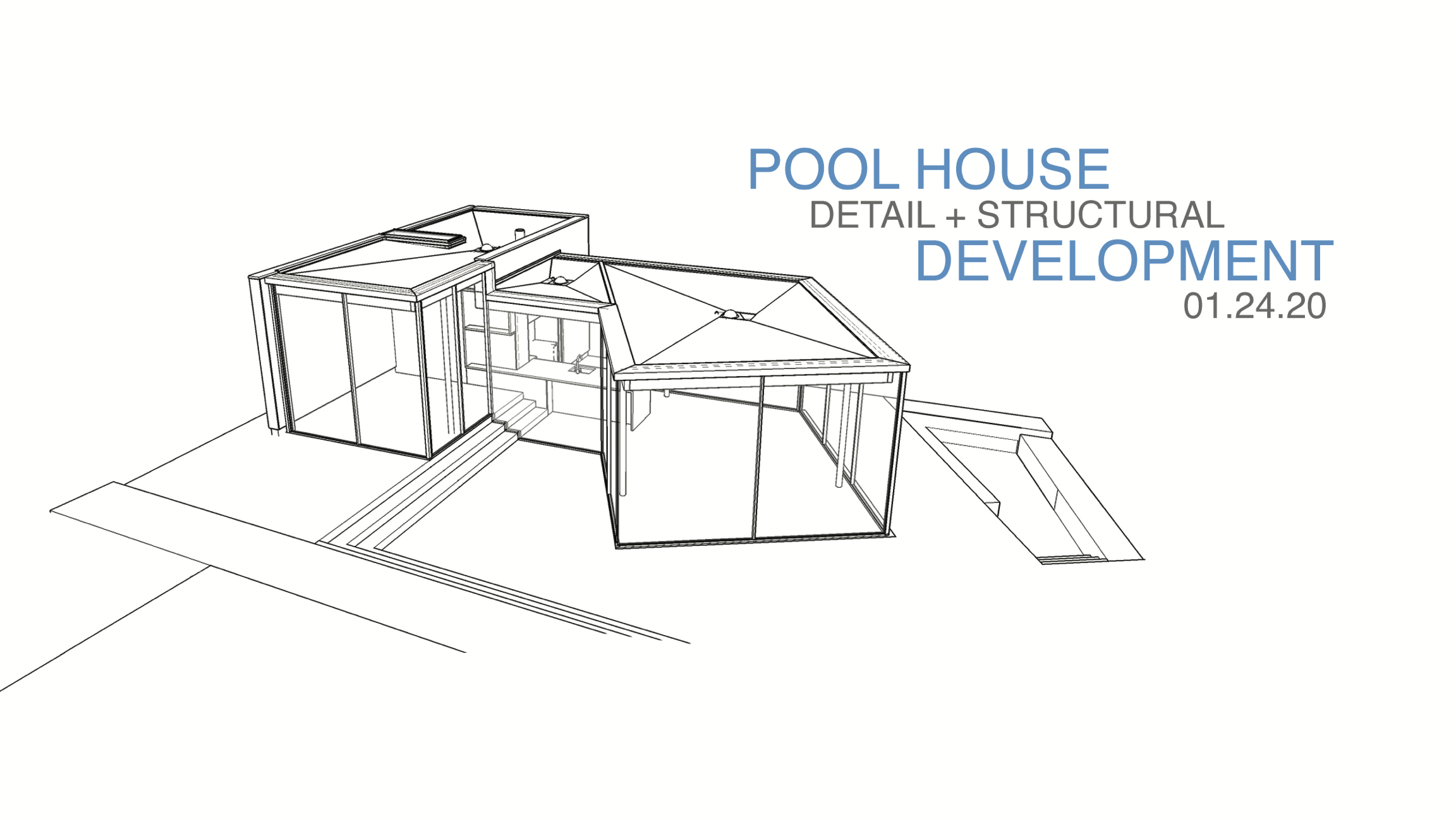
This jewel of a building, set in the coastal mountains of the Bay Area, is simple in form and complex in execution. Transparency and simple appearing connections require sophisticated structural design and integration with finishes.
We use digital modeling programs, hand sketches and CAD drawings to investigate and finalize all of the key connections, in support of the design idea.
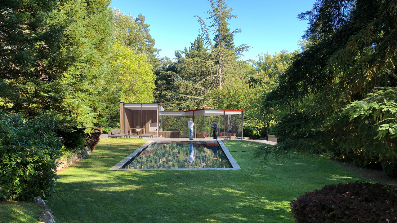
The Poolhouse is designed as a stunning replacement for a non-descript older poolhouse and equipment shed. The new Poolhouse and pool are now a featured view from the Living room and it’s terraces to the east.
The structure is meant to feel as though it’s an open-air pavilion, with as little strucure evident as possible.
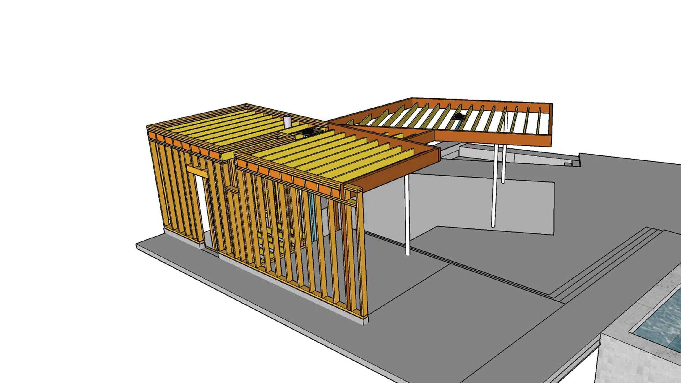
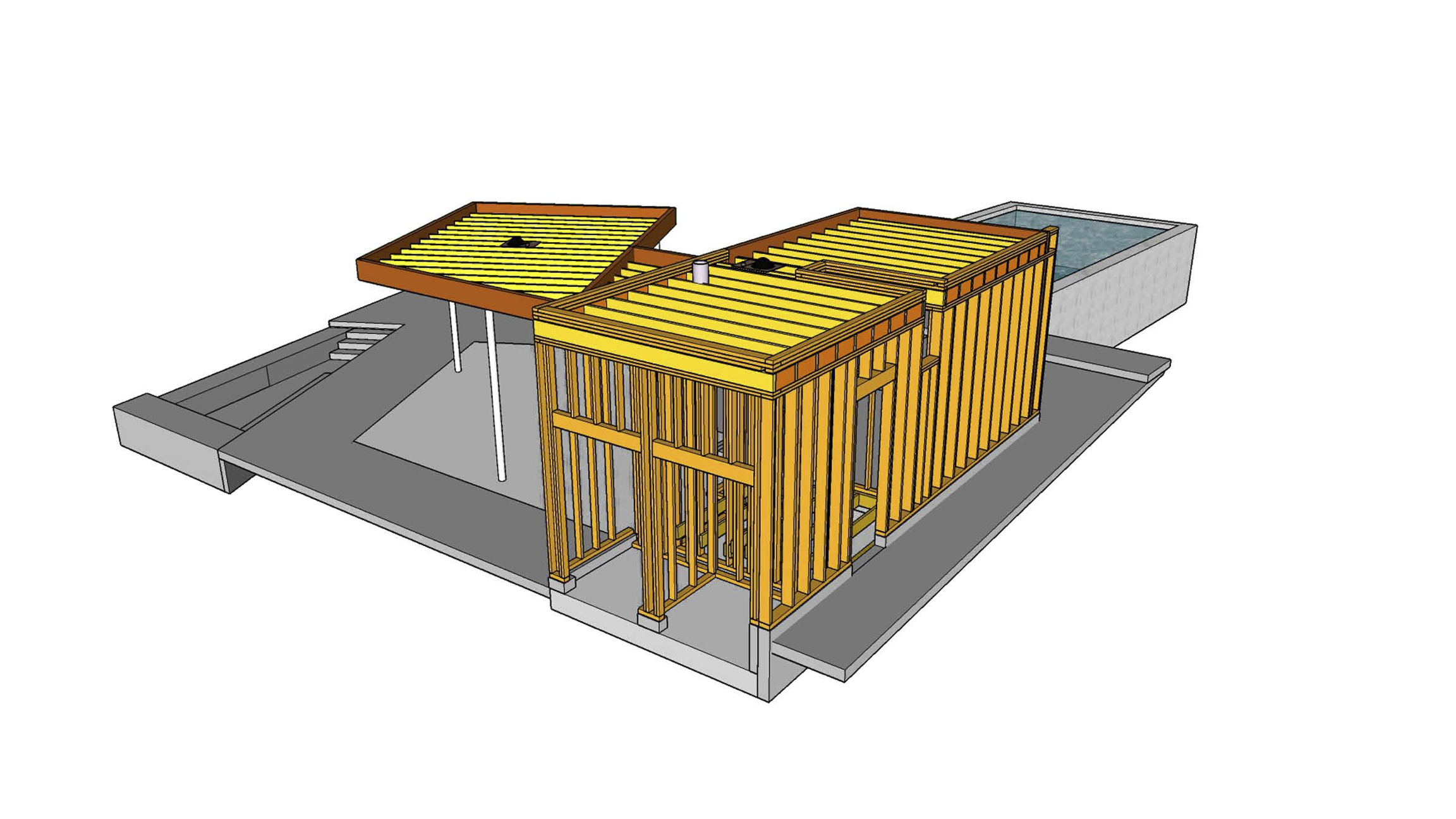
We reviewed the structural system in a digital 3d model to confirm the interactions of the various structural materials; steel (red), wood framing (orange), and concrete (grey).

After the main structural elements were defined, we were able to focus on the architectural details that need scrutiny.
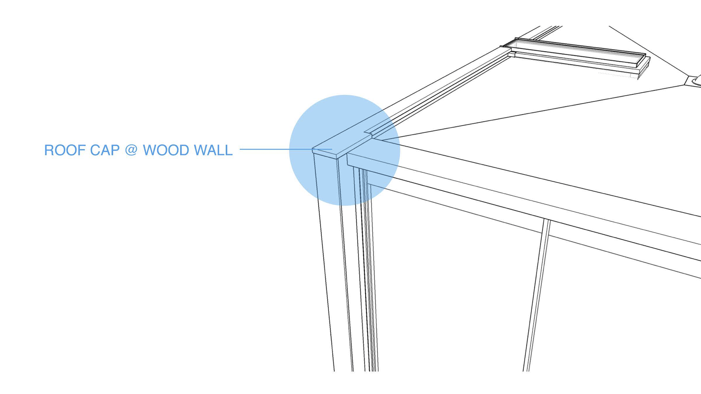
Typically, we start at the top of the building with the important edge that marks the profile against the sky. In this case, a very secure but minimal metal edge cap was studied.
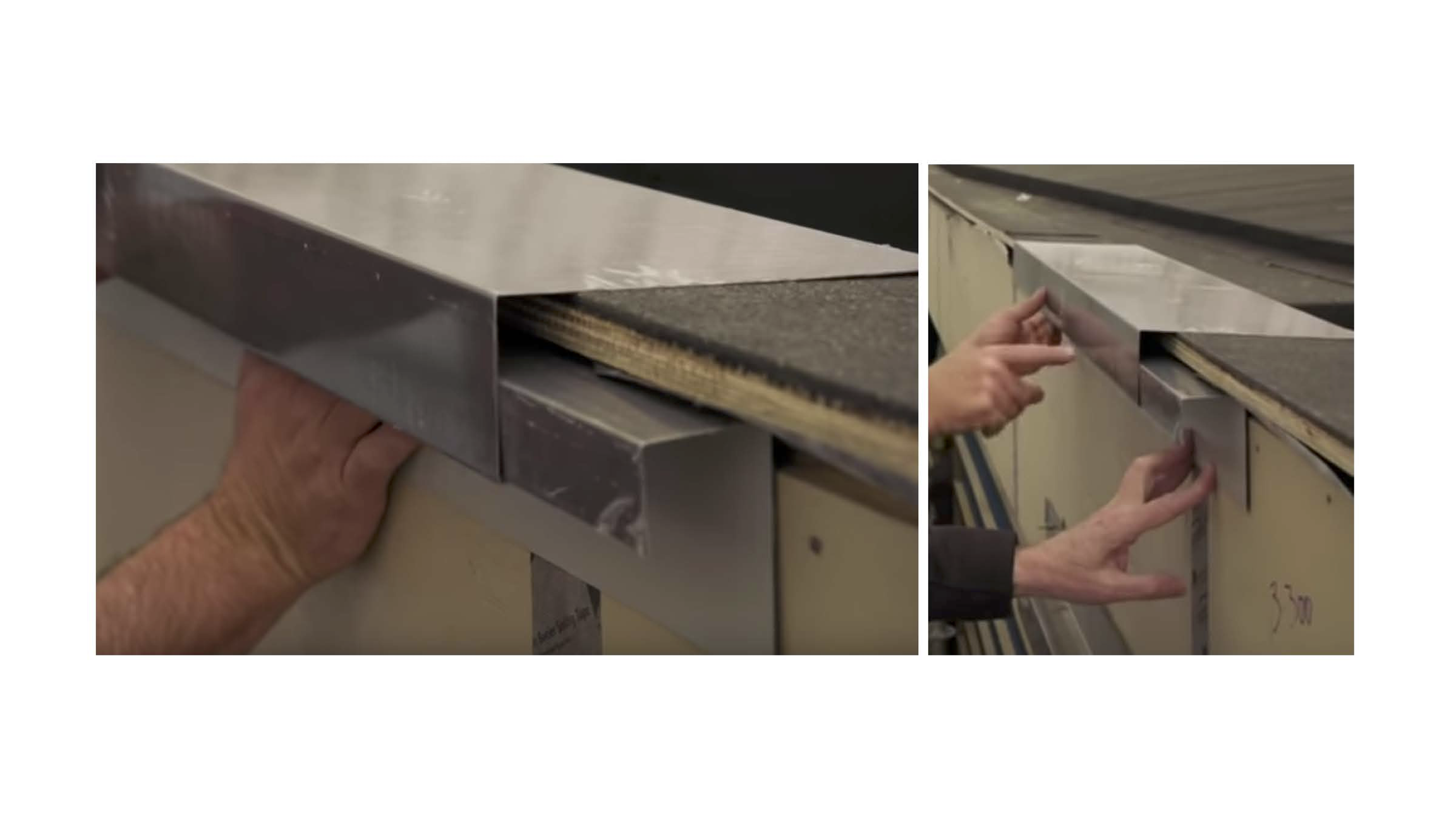
Often actual material models are essential to help confirm the visual and technical integrity of the detail. In this case we used sheetmetal patterns of the correct size to help evaluate the look and feel.
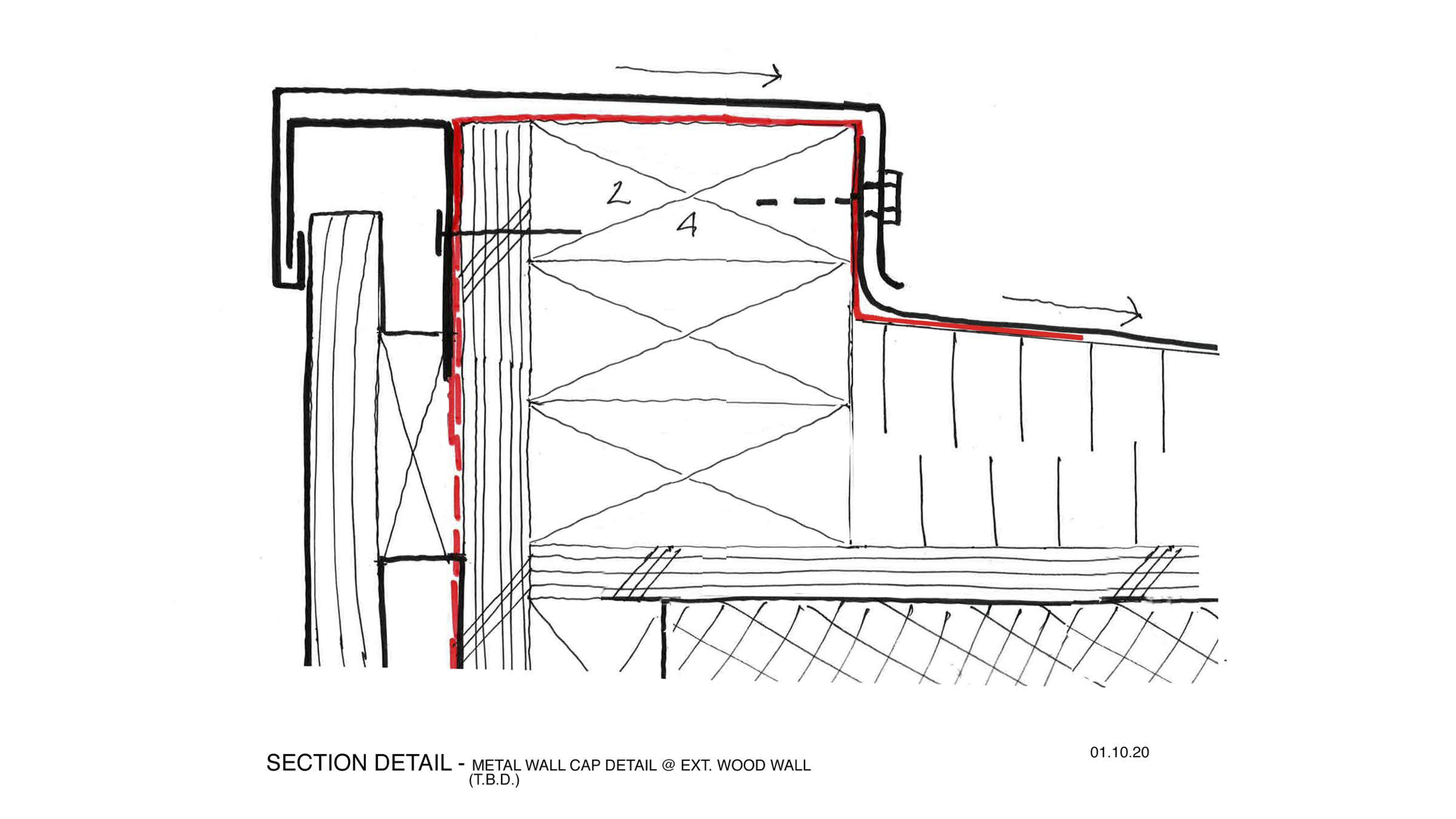
After verifying the basic dimensions of the sheetmetal mock up, we investigated further, in sketch section form, how the metal would be incorporated into the waterproofing system.
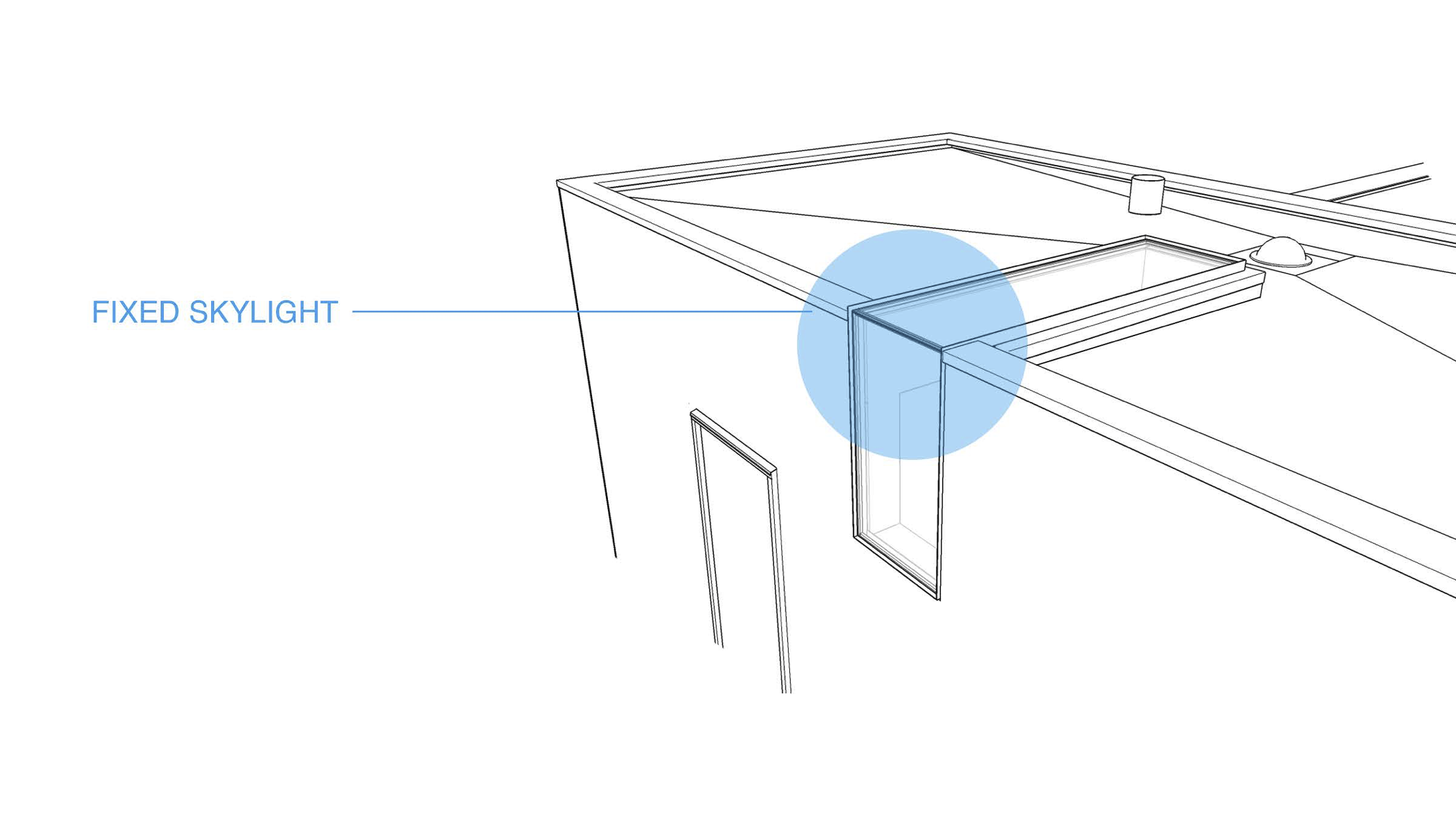
Designing a custom skylight that transforms into a window required a bit of investigation.
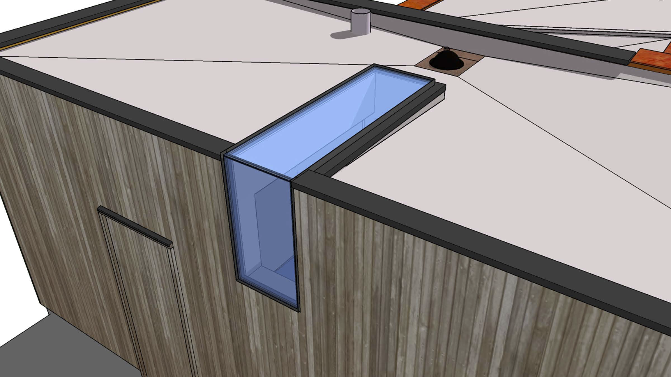
A rendered view of the desired outcome.
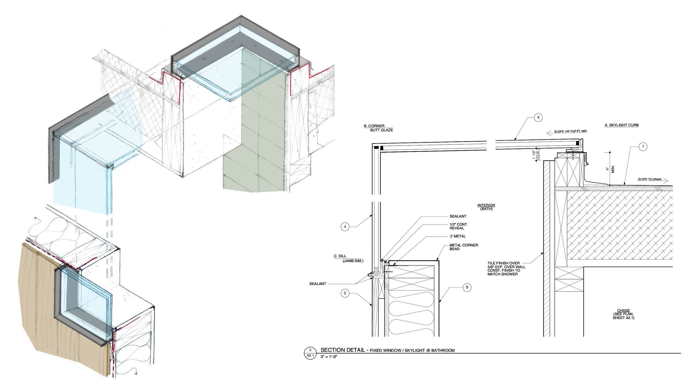
Using 3-d hand sketch sections and CAD sections to scale, we investigated all of the important conditions together.
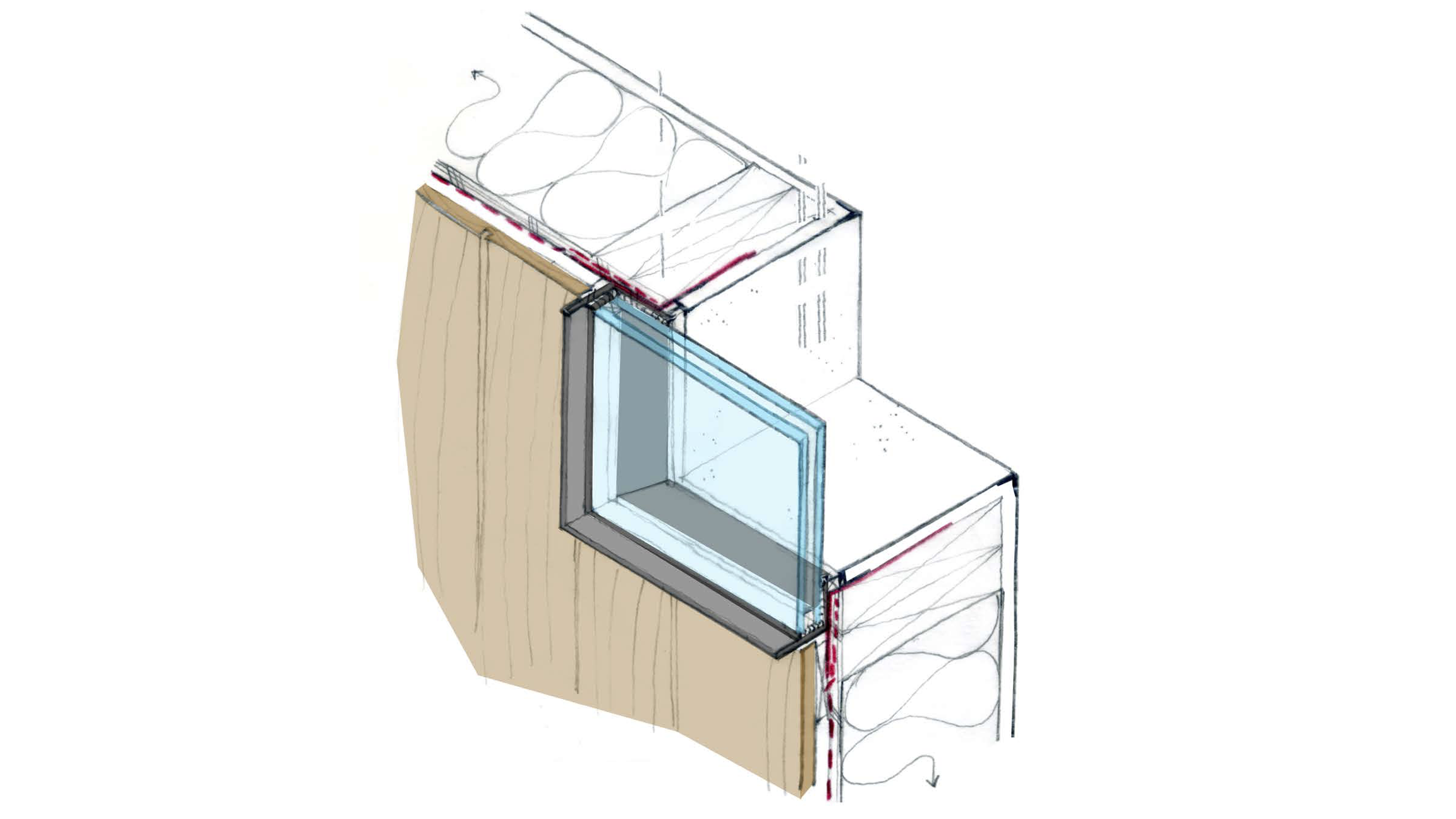
The window portion of the assembly is designed as an “L” shaped metal angle frame receiving a fixed double-glazed panel set in sealant.
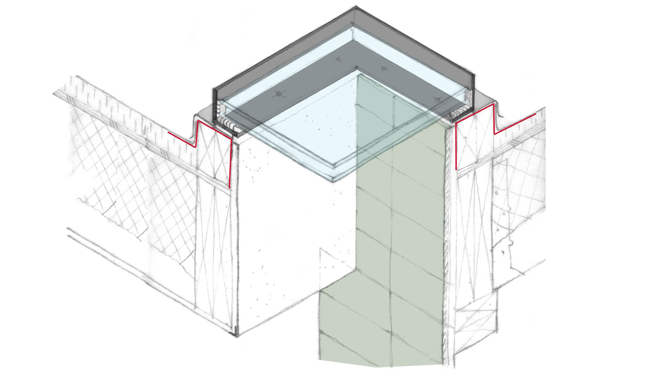
The skylight portion of the assembly follows the arrangement determined below for the window portion.
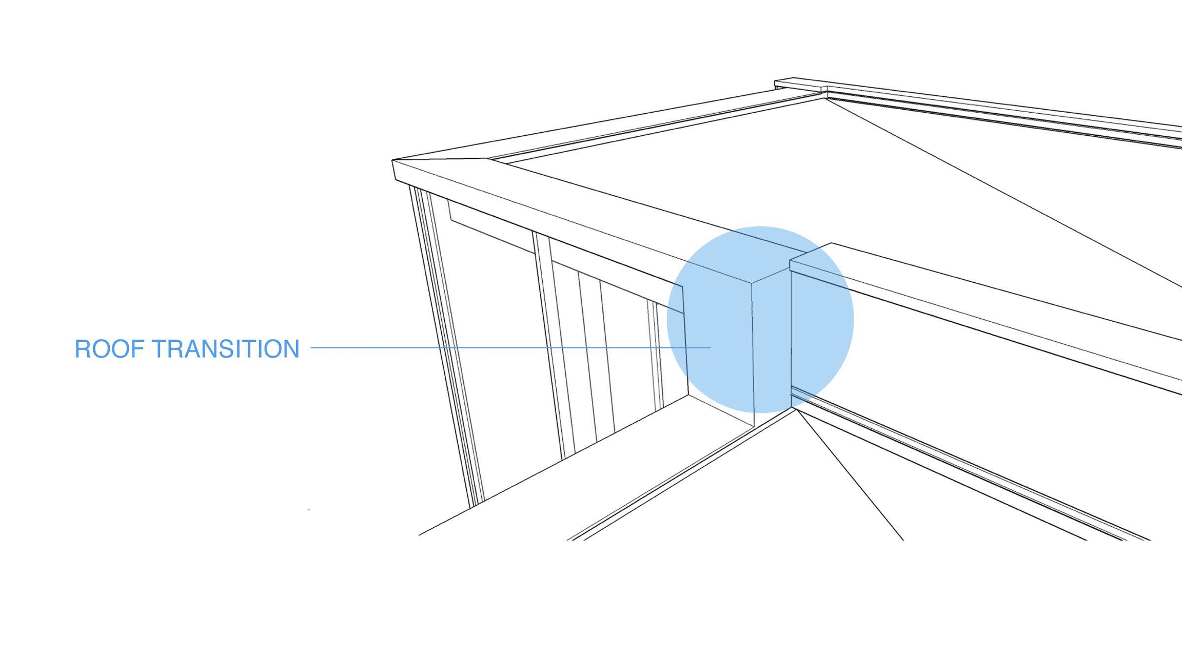
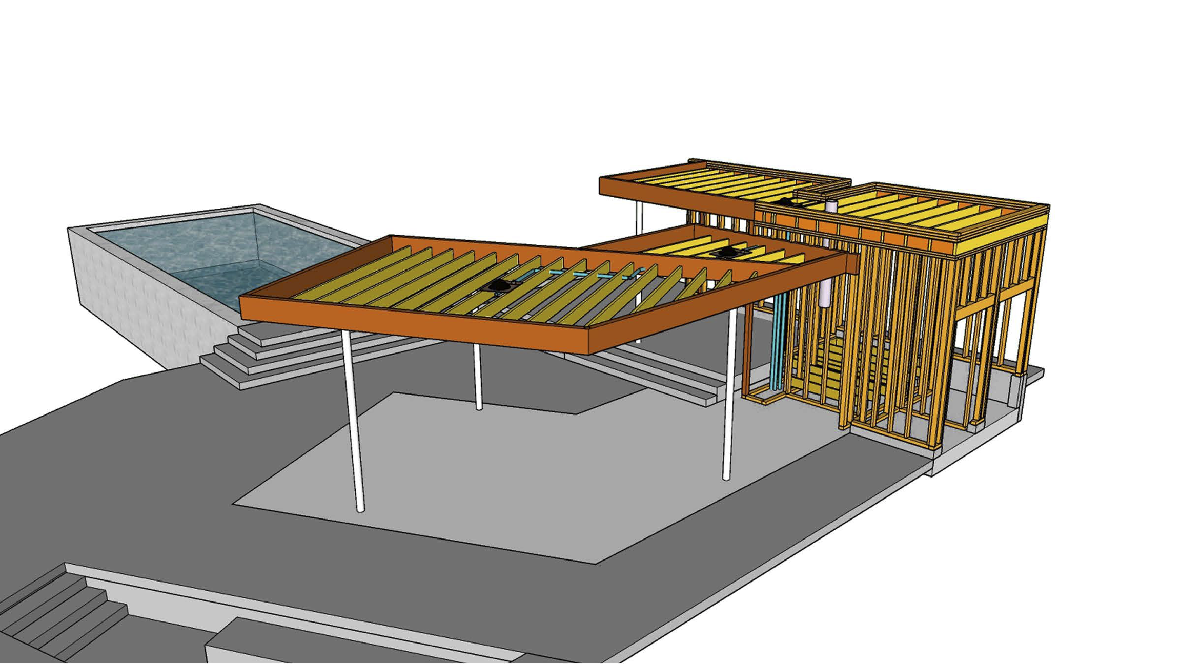
The varying heights of the roof elements of the building, tailored to just skirt under the warped height limit above natural grade, create some challenging finish transitions.

The underlying structural “bones” of the building.
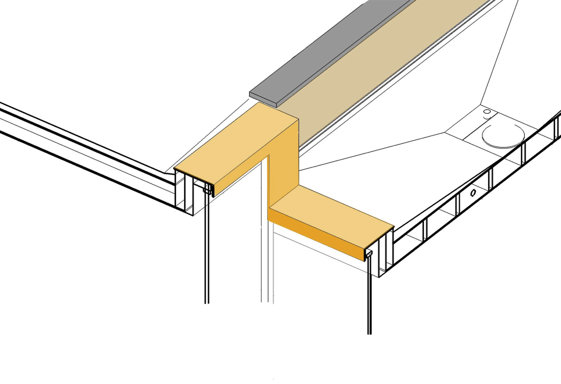
The sheetmetal cap has to change direction 90 degrees in plan and also in height, while tying together seamlessly.

One of the cornerstones of the design is the thinness of the apparant roof line. We chose to use the sheetmetal cap, made of CorTen steel, as the catchment of the top of the sliding door frame. This allowed the glass to rise to within just a few inches of the top of the building, accentuating the theme of transparency.
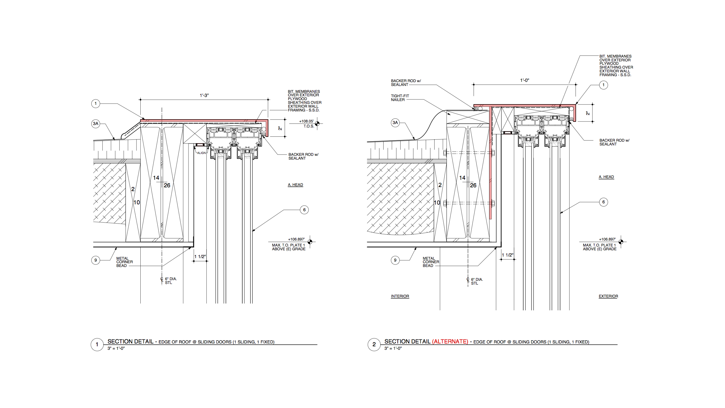
In working with the Builder and Structural Engineer, we came up with alternative ways to achieve the desired outcome.
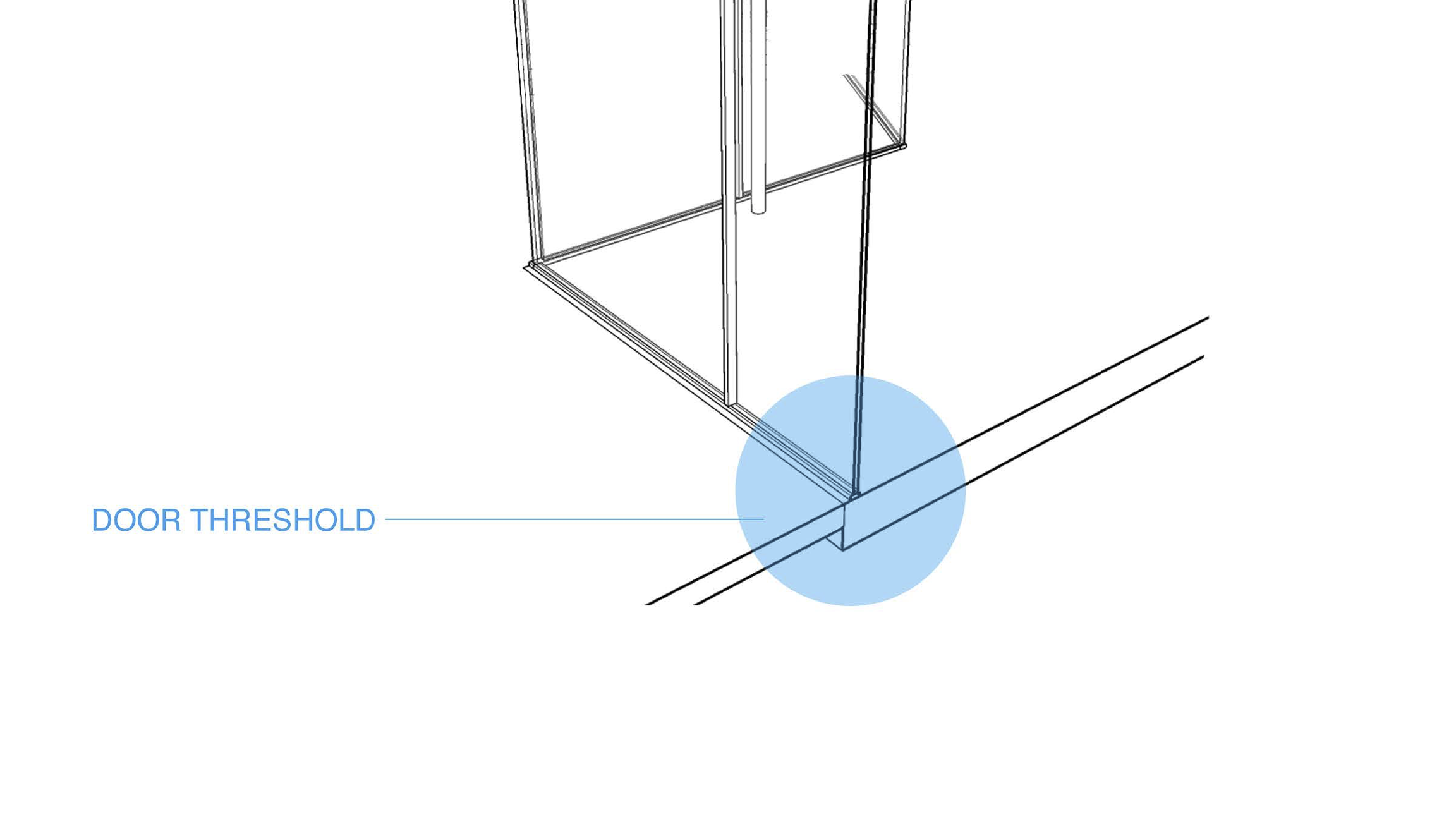
We next investigated the interaction of the sliding door threshold and finished interior and exterior paved surfaces at the base of the building.
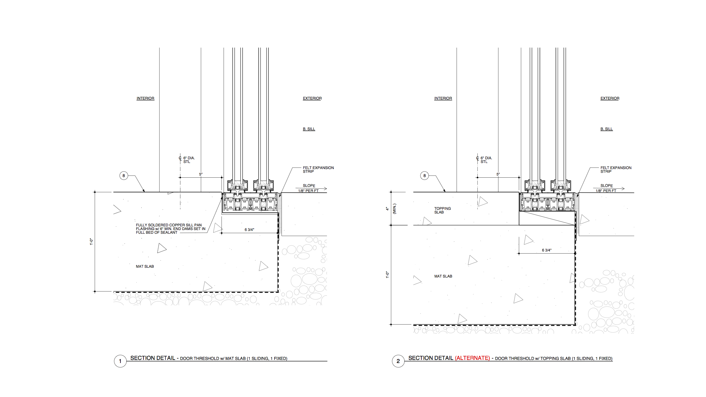
Two alternative ways to embed the sliding door draining threshold into the paving.
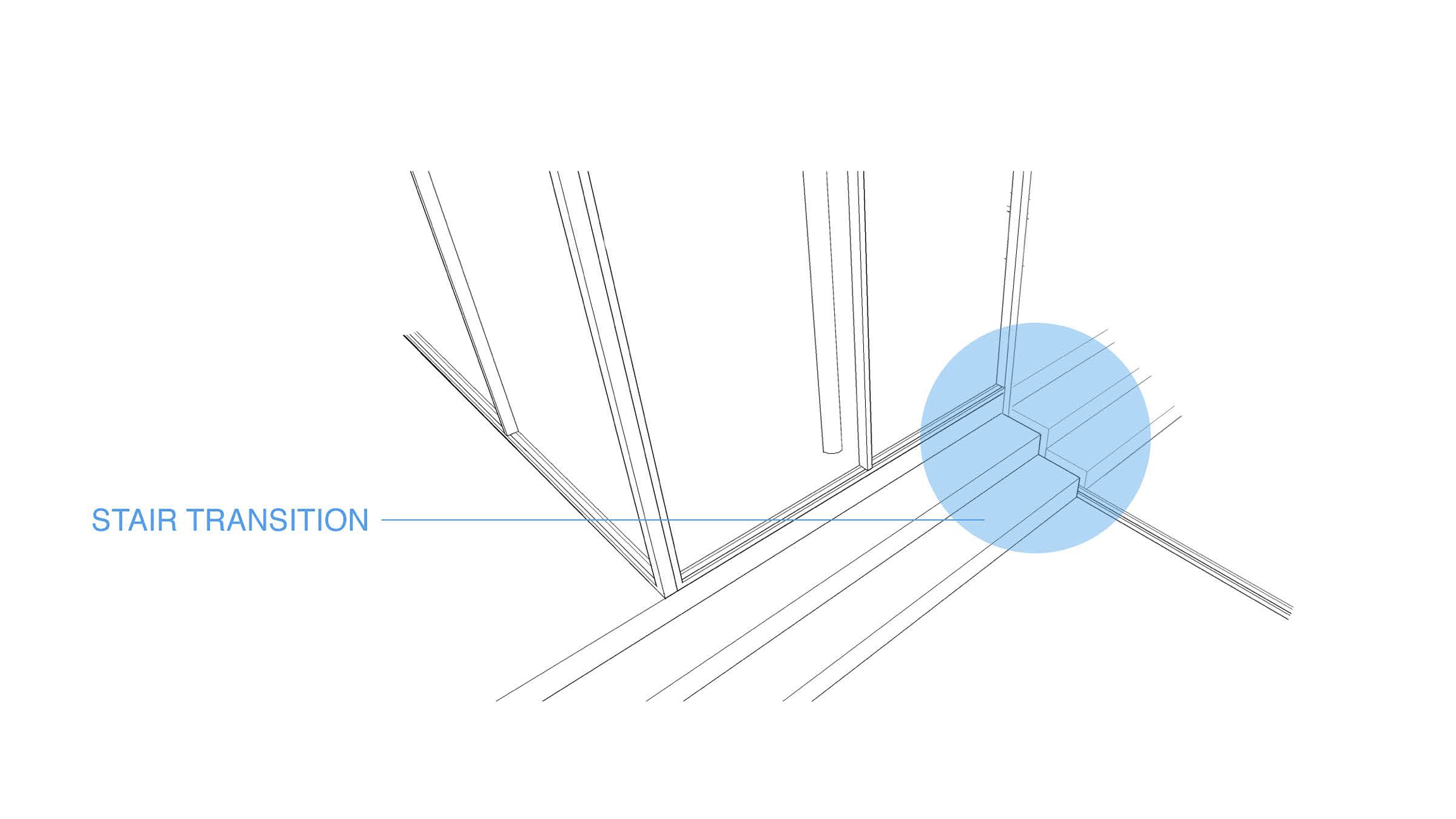
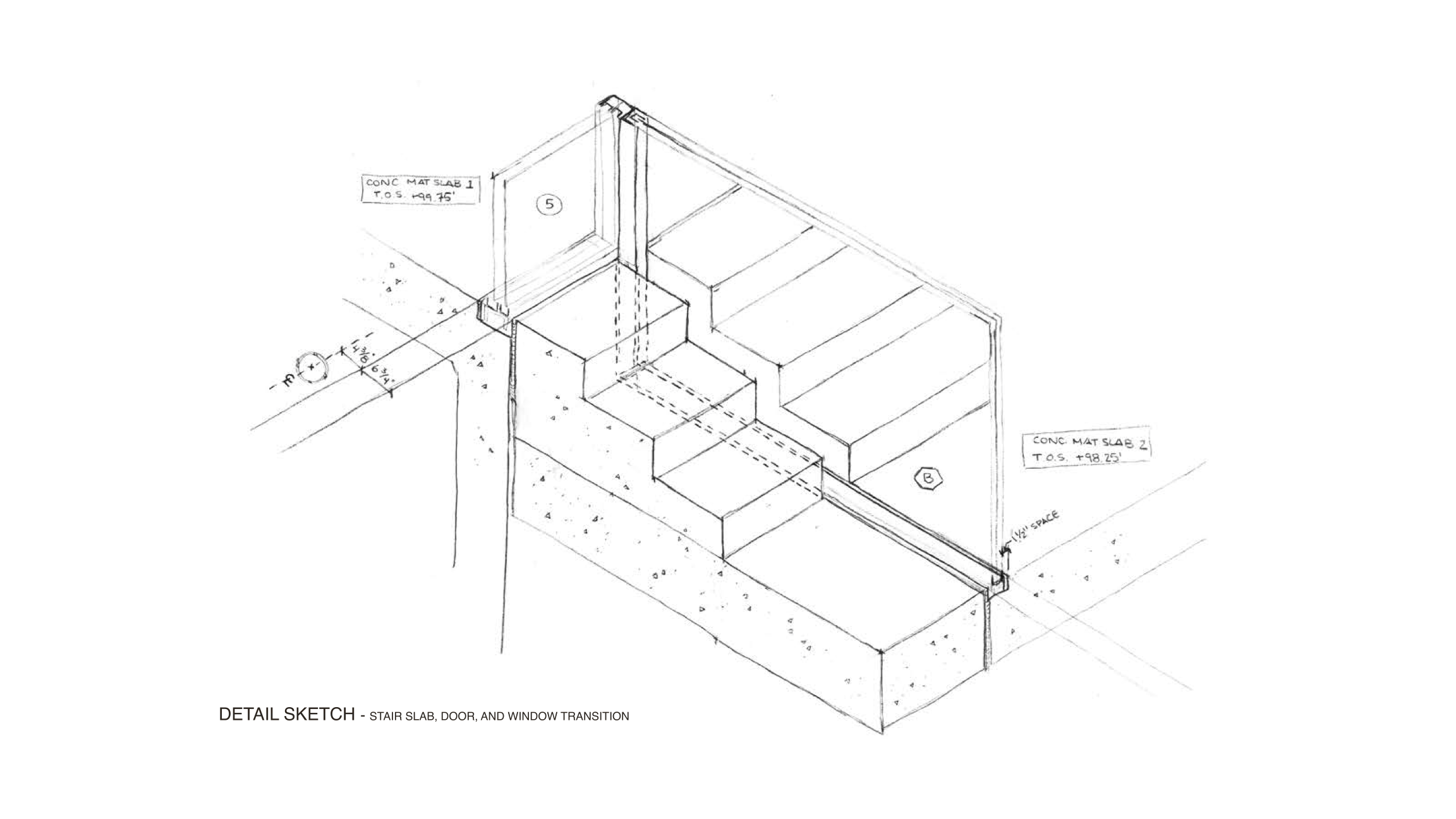
Finally, the interaction between the interior and exterior stairs was explored in relation to the rectilinear glazed door panel.