From Hand to Computer: Drawings for Communication
by Rebecca Firestone with Mark English AIA | Editorials
Earlier, we showed the power of hand drawings as communication tools. Now, we do the same with CAD – taking it to the next level.
In previous articles, we’ve explored the power of hand drawing for working out design problems, communicating with clients , and for communicating intent to contractors in the field. The same detail that would take 2 or 3 “flat” drawings to describe can be grasped immediately a 3D or isometric sketch, with less mental effort.
Hand drawings are faster to do, too. The same detail might take 15 minutes to hand sketch in rough dimensions, but over an hour to model in CAD with dimensioning and calculated parameters.
So what happens once you’ve communicated your intent, or you’ve worked out how the building elements should really go together? The next step is to go ahead and create that CAD model and add precision scaling and dimensions. These renderings can be used in construction drawing sets, which can be legally binding, whereas hand drawings (typically) cannot. As with hand drawings, renders can help the builder understand how things go together, the operation of moving parts, and the order of assembly.
Fontana Apartment
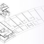
This luxury apartment make-over, featured in its completion on Mark English Architects’ main web site, has a clean, curvilinear feel. The drawing technique we want to highlight here is this Escher-like trick: an isometric kitchen where half of it is floor plan (looking down) and half in elevation (popping out a wall).
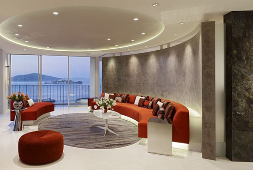
This apartment was redone by Mark English Architects and features an elliptical living room with a hand-plastered wall for enhanced acoustical experience during live music jam sessions. Image: Mark English Architects

-
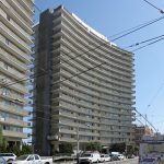
- The Fontana luxury apartment building is located at 1000 North Point in San Francisco. Its gently sweeping curves add grace to the skyline, and the back side offers unparalleled views of the San Francisco Bay.
-
- The apartment is at the end of the floor, about halfway up the tower. Image: Mark English Architects
-
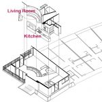
- Composite image showing insertion of an isometric view of the interior onto the floor plan. Image: Mark English Architects
-

- The completed kitchen. Images: Mark English Architects
-
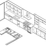
- In this hybrid isometric view, the kitchen shows one side as a 3D elevation, and the other side as a 2D floor plan. Image: Mark English Architects
Quick Gestalt
Sometimes the sheer clarity of a good 3D rendering can add validity. Notice that these renderings are not isometric 3/4 views, but instead utilize 2-point perspective with a horizontal vanishing point while the vertical members are rendered isometrically (no vanishing point below). The result gives the viewer an enhanced sense of place.

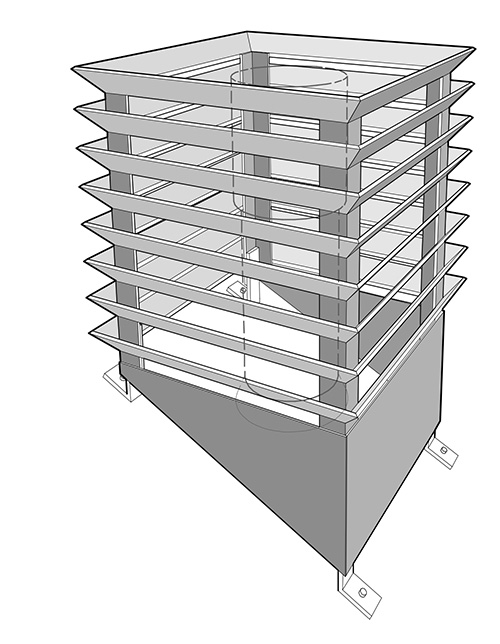
This steel chimney surround assembly gives a clear picture of how it’s attached, and also shows the chimney itself ghosted in the middle. Image: Mark English Architects

-
- View of an entryway. Note the inclusion of the fasteners inside the construction. Image: Mark English Architects
-
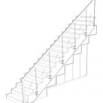
- Three views of the same stair, on a single page, helps convey a sense of place to clients. Image: Mark English Architects
Desk Legs
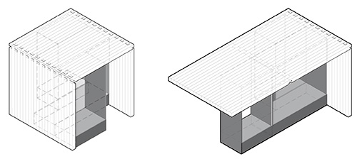
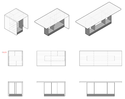
A combination of isometric and flat views (top-down and elevation) shown on the same page gives a better sense of how to assemble this custom-designed desk. The two desks are different heights. Readers don’t have to spend time flipping back and forth between 3 or 4 different pages.

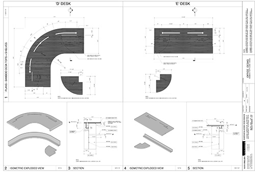
This page shows how the desk tops and lower shelving beneath fit together, for two desks labeled “D” and “E”. For each, the top-down view at the top of the page is complemented with an isometric on the left, and a cross section on the right. Image: Mark English Architects

-
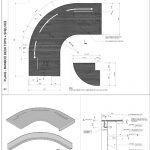
- Close-up of Desk “D”. Image: Mark English Architects
-
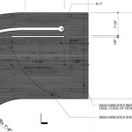
- A closer zoom on Desk “D” shows how the rounded shelf beneath fits underneath the top. Detailed instructions and callouts guide precision assembly. Image: Mark English Architects
-
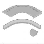
- Close-up of the bottom isometric for Desk “D”. Image: Mark English Architects
-
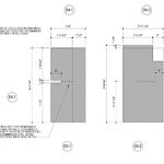
- Close-up of the cross section supports for Desk “D”. Image” Mark English Architects
-

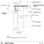
- A second page shows the custom designed steel legs for Desks “D” and “E”. Juxtaposing the isometric and section views allows readers to figure out easily how it goes together without having special training to read technical drawings. Image: Mark English Architects
-
- Close-up showing assembly for a single desk leg for Desk “D”. Image: Mark English Architects
Fold-Up Dining Room Table
This example shows a dining room table designed for a tight space. The leaves each fold out individually, with a base that also rotates out underneath the table on hinges.

Fold-up dining room table, showing isometric views, top-down, and sections on a single sheet. Each leaf and base folds out independently. Image: Mark English Architects
Fasteners in Assemblies
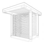
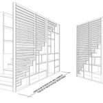
Mechanical assembly diagrams include fasteners to show how the whole thing goes together, and sometimes visual indications for the operation of moving parts. In this vertical trellis design, the top portions of each trellis fold down to allow for trimming of the vines without having to use a ladder.

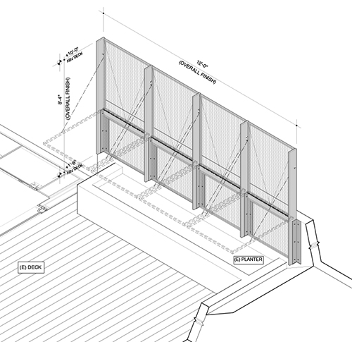
A fold-down deck trellis. Image: Mark English Architects
IMAGE THUMBNAIL GALLERY

-
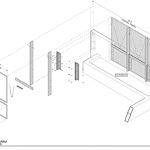
- Assembly diagram for fold-out trellis. Image: Mark English Architects
-
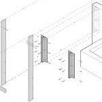
- Close-up assembly diagram for fold-out trellis. Image: Mark English Architects
-
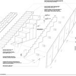
- An exploded diagram showing stair construction. Image: Mark English Architects
-
- Same stair, assembled. Image: Mark English Architects
Conclusion
Thoughtfully presented CAD renders require effective presentation skills as much as design competency. Taking the time to conceptualize the presentation results in a more readable drawing set that serves multiple audience levels and project needs.