

Understanding Complexity at a Glance: Hand Drawing as Tool for Technical Communication
by Rebecca Firestone with Mark English AIA | Work/News
Hand drawing is not just a holdover from architecture’s pre-digital past. Even today, hand-drawn sketches are an indispensable tool for communication, problem-solving, and rapid exploration of new ideas. Greg Corbett, Architect at Mark English Architects, shares hand drawing techniques for creating 3D illustrations during project development.
In recent decades, the architectural profession has moved away from hand drawing to an increasing reliance on digital renderings and CAD drawings. There are times, however, when computer-generated drawings are actually more expensive in terms of time, and a hand sketch can convey understanding more effectively than a computer-generated drawing.
Everyone on the project team, including the client, needs to understand the design. Image: Mark English Architects
Why Hand Draw?
Architectural drawings, renderings, and other instructions must communicate effectively in order to forestall costly mistakes. Architect Greg Corbett observes: “It is an advantage to builders if they can understand a complex detail at a glance by looking at one drawing, as opposed to looking at several drawings and piecing the detail together.” Isometric hand sketches can be a quick and effective tool to illustrate ideas at any stage of the design and construction process.
First Example: Fireplace
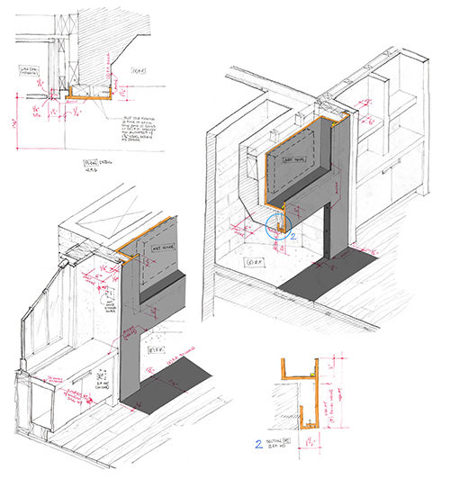
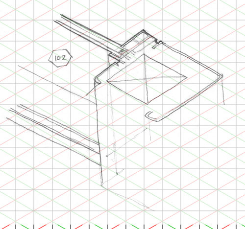
This drawing, traced over an isometric grid, was used to explore the relationship of a proposed cold-rolled steel fireplace finish with a lighted art niche, creating a study in both plan and section. Image: Mark English Architects
A way to simplify the process of generating hand-drawn isometrics is to use an isometric grid and begin “building” the drawing with the use of trace paper. “The above drawing of an existing fireplace replaced with a proposed cold-rolled steel fireplace finish and lighted art niche is a study in both plan and section. How the steel components relate to the side cabinets, wall, and floor are illustrated with the intent to discuss the design with the fabricator in order to determine the right approach to fabrication. This pencil study took a fraction of the time to construct, compared to the time it would have taken to model a similar drawing on the computer.”
Corbett observes, “In many instances, in order to figure out how a detail comes together, you have to look at three or four 2D drawings – sometimes more. I have found that a hand-drawn isometric can be a single source communication tool where the four 2D drawings are explained quickly. in creating this drawing, some analysis of consultant drawings is necessary – which always brings clarity and sometimes, questions – which are communicated back to the consultant.”
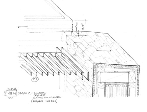
Second Example: Clearstory Window
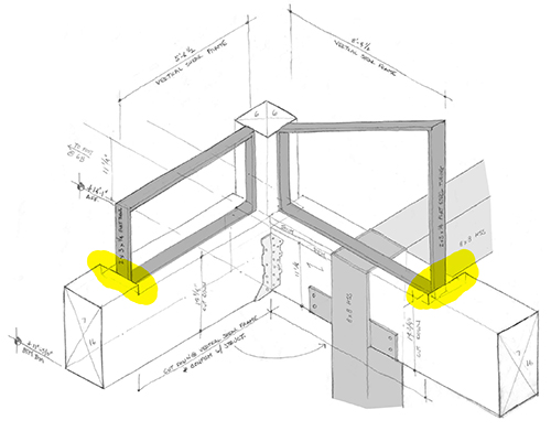
This isometric hand drawing is an examination of a somewhat complex corner, where clearstory windows come together and interact with beams, vertical shear frames, and a steel column. It is easier to see that the windows are sunk into the beams in the isometric drawing. Image: Mark English Architects
Another example shows a corner with clearstory windows. “To understand the structure and interrelationship of elements at this clearstory window corner, one has to look at four different structural drawings and details as well as the window jamb, sill, and head condition,” explains Corbett.
“In a single drawing, the isometric reveals what might be considered a ‘Frankenstein’ of parts coming together. Given that the structural engineer has called for the use of shear frames, the beams need to be notched down at the corners as illustrated, in order for the new window sills to align at the same height along the tops of the beams. The scale and proportion of the components in this drawing are not important,” explains Corbett, “What is important is conveying to the builder that the beams require notching before being set into place.”
“By doing this isometric study, the architect gained a better understanding of the condition, and was able to convey to the builder the different elements coming together.”
Third Example: Window Nook with Storage Bench
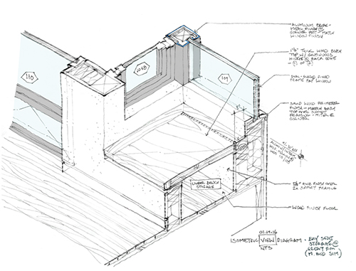
Isometric drawing of a seating nook. The storage bench has a hinged fold-out lid. Image: Mark English Architects
A third example shows the construction of a bench and seating nook at a bay window. “Unlike 3D modeling on the computer, the elements of a 3D hand sketch do not have to be precisely measured out or quantified. Visually, the proportions and relationships are the most important elements to consider. In the above illustration, the relationships between the bench top and the side walls, window, wall base, etc. are clear to understand even though the dimension are not precisely measured out. The time it took to produce this drawing was greatly reduced when compared to what a modeled computer image would have taken.”
Corbett outlined three main purposes of hand drawings generally:
- First, the drawings help the designer to work out a problem.
- Second, these drawings communicate intent to the fabricator quickly.
- Third, the drawings can illustrate design ideas for an owner or client.
For clients, isometric or perspective hand drawings can help them understand what is being built. In this case, a drawing conveys a sense of immediacy, and creates in the clients’ own mind a sense of place.
Tools
These hand drawings are not freehand. They’re done on standard architectural trace paper, using pencils. Corbett uses several aids: isometric and perspective grids, or sometimes tracing over computer models to add more detail. The resulting drawings are scanned and colorized in a computer paint program for further clarity. (Although “real” CAD systems can be expensive, and difficult for newbies to learn, Google SketchUp is a popular drawing tool available for free, and even non-drafters can pick it up quickly.)
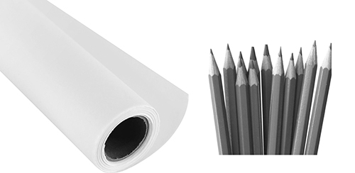
The basic tools for these isometric sketches are simple graphite pencils and trace paper.
Isometric Grids
Isometric drawings are a great way to rapidly explore the implications of a design. They can help the architect think things through before the drawing even goes out to a third party. The key is re-usable isometric grid paper, which serves as a trace guide. Making your own is easy to do if you can print in color on 11×17 inch sheets. (Here’s a PDF of Greg Corbett’s isometric grid template: 1-8-grid)
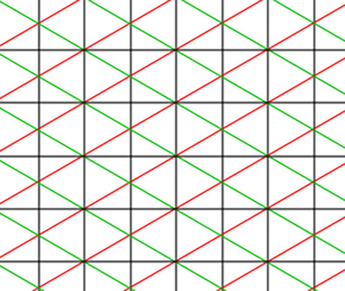
Close-up of Greg Corbett’s 11×17 isometric grid paper, useful as a drawing guide. Image: Mark English Architects
Use a sheet of trace paper similar to this item to make your drawing. You can also purchase this at art stores.
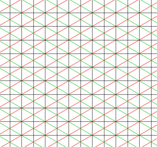
To make quick isometric hand drawings, use pre-printed isometric grid paper and trace over it with a pencil. Image: Mark English Architects

“It helps to make the isometric lines a different color so that they are visible through the trace paper.” Here, the verticals and horizontals are black, while one diagonal is red and the other is green. Image: Mark English Architects
A Grid Trains the Hand, and the Mind
“A line will tend to curve up or down as you draw it out. By using a grid as a guide, I have found that you can create the isometrics quickly and not have to worry about this happening. After using the grid for a while, your hand doesn’t seem to curve as much and you don’t have to be as reliant on having a grid and trace handy. On-the-spot 3D sketches in the field become much easier to produce.”
Corbett observed that the more of these 3D drawings that he does, the easier it becomes to visualize in 3D without as much mental effort. We speculated together that it could be the motor engagement, i.e., the actual physicality of the movements of hand drawing, that somehow reinforces a sense of human agency in a way that machine interactions do not. The ability to master the world by working with our hands is, after all, one of the key elements of being human.
Keeping Hand Drawings True
What about using a ruler? “A shaky line actually helps,” says Corbett.

Tracing over a grid helps to keep freehand drawings looking true. Image: Mark English Architects

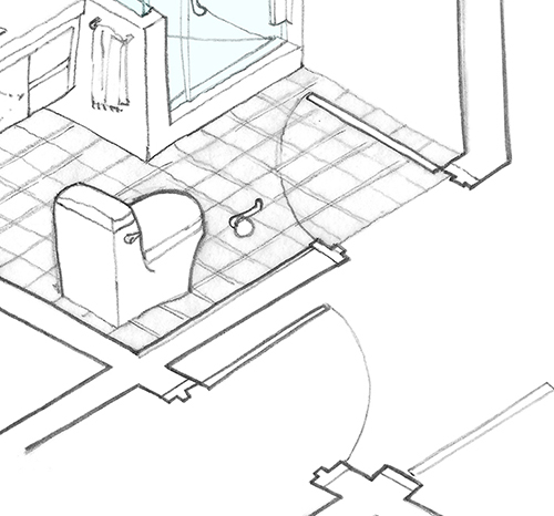
This particular close-up of the preceding drawing shows another trick: mixing 2D and 3D floor plans. In this case, the in-swing arc of the door at the bathroom entry is outlined on the floor. Image: Mark English Architects
Varying the Line Weight
Line weights also pop out a lot more in hand drawings, especially with graphite. Varying line weights can be done on the computer as well, but takes longer than just drawing it out on paper using a thicker lead.
Varying line weights help make a hand drawing more cohesive by visually grouping larger elements. Image: Mark English Architects
One-Point Perspective
Corbett uses a one-point perspective for smaller spaces such as bathrooms, to show positioning of fixtures and other elements such as towel racks.
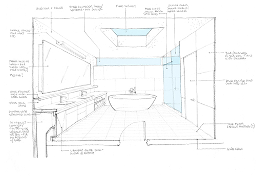
A one-point perspective bathroom sketch. Note that the in-swing of the door is shown as if on a floor plan. Image: Mark English Architects
Two-Point Perspective Grids
Two-point perspective grid paper (download: 2p-grid) is also useful for tracing. A two-point perspective trace can help visualize a three-dimensional structure, such as a building, unfolding in space.

Example of Greg Corbett’s two-point perspective grid guidelines. Image: Mark English Architects
Tracing Over a Machine Render
Machine renders are good for setting custom perspectives. The designer can then trace over the machine render, to explore additional details.
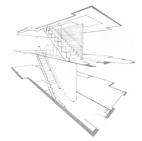
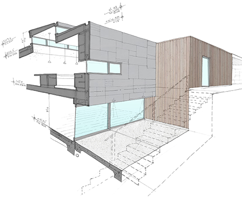
This exploded view showing a three-story residence stripped down to the proposed stair and floor plan diagram was created by tracing over a computer-generated model (not shown). Image: Mark English Architects
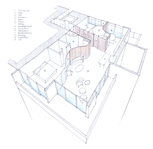
Hand sketching over a computer-generated line drawing is useful for exploring things like interior wall and furniture placement, and can help clients visualize alternatives. Image: Mark English Architects
3D Cross Sections
Cross sections or “sections” are often done to show the composition of materials inside a wall, floor, or ceiling: insulation, structural components, layered surfaces, finishes, and other non-visible features. A designer can also use 3D cross sections to show the composition of place inside a home.
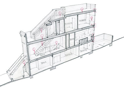
A hand-drawn cross section of a three-story home shows stairs and circulation, lines of sight, and changes in floor level. Image: Mark English Architects
Developing a House Through Drawing
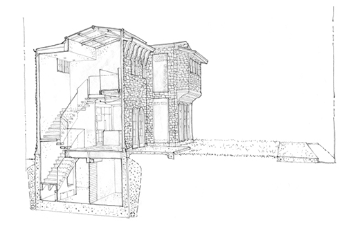
Multiple cross sections through the same space can show a progressive series of views, and can be used to develop areas of an entire house. The following project is a three-story house with a deep basement and a central spiral stair. “The central stair was tricky to show,” says Corbett.

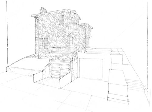
On this project, hand drawings explore the circulation in another three-story home. First, the front of the house. Image: Mark English Architects

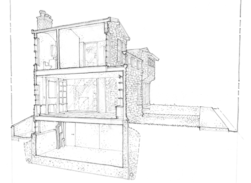
A section near the front side of the house shows the basement, first floor, and upper story. Image: Mark English Architects

A section near the center of the house shows stairs and circulation. The stair itself, with its custom glass rail, was also extensively explored through further drawing details. Image: Mark English Architects
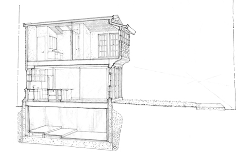
A section towards the rear side of the house shows the rooms on the other side of the central stair. Image: Mark English Architects
Stay Tuned…
Further articles will explore specific problem-solving examples.


Skylight case study | The Architects' Take
12. Dec, 2016
[…] a recent article, The Architects’ Take introduced some hand drawing techniques and showed how these drawings could […]
Inclination and Evolution: A Stair Design | The Architects' Take
30. Dec, 2016
[…] a main floor, and an upper floor. We viewed some 3D sections of this project in a previous article that introduced the power of hand drawing. Now, we focus on one particular feature of this home, […]