
Structural-Architectural Integration
by Rebecca Firestone with Mark English AIA | Mark English Architects, Work/News
Using 3D visualization tools and other methods, one design team worked out a cost saving of $220K without sacrificing the building’s structural integrity.
In architectural design projects, structural engineers and other consultants make decisions based on the plans and the initial direction that they receive from the architect. In one project, a private home, the structural engineer chose to rely on steel – a safe structural choice. But steel is expensive. The architect didn’t want to pass unnecessary costs onto the client.
Reducing the Steel
The structural engineer is responsible for ensuring that the architect’s design has adequate framing to support the weight of the building. Unless the architect specifies a framing type as part of the design, the structural engineer can choose the framing system – for example steel, wood, or reinforced concrete.
Greg Corbett, Staff Architect at Mark English Architects in San Francisco, explained how one private home design needed refinement in order to reduce the amount of steel.

Steel framing is shown as red in this structural model done in Sketchup. Image: Mark English Architects
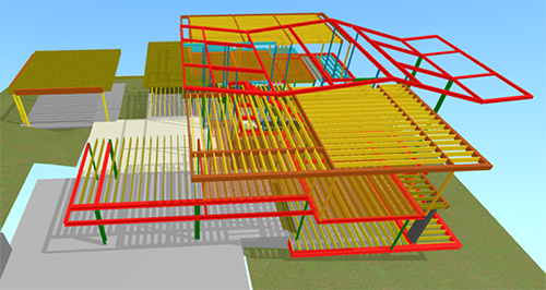
In order to reduce the amount of steel, the architect built a structural model of the engineer’s proposal in Sketchup and invited the engineer to come in and review it.
Did the gray areas for the upper roof plan really need to be steel? Image: Mark English Architects
One drawing showed two gray areas from the roof plan as all steel. The architect wanted to know if wood could work instead. However, any material change could alter the height of the section. Things had to match up. Creating a structural model allowed the team to easily spot these small alteration before they cropped up in the field later on.
Kubity Visualization App
The architect employed a mobile app called Kubity that designers can use to share 3D structural models in either Sketchup or Revit, adding virtual-reality features such as walkthroughs, fly-throughs, and augmented reality. The structural engineer scanned a QR code that downloaded the Sketchup model onto his phone for review prior to the meeting.

Kubity is compatible with Oculus Rift and HTC Vive virtual reality systems. Users can walk through architectural designs so that owners, engineers, architects can all fully envision the project.
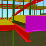
The architect used color coding in the Sketchup model to call out different material conditions: Blue for missing pieces, red for steel, yellow for wood, and purple to indicate an issue with that portion of the structural design regardless of the material.
The architect used Kubity to import a Sketchup model for viewing on mobile devices. Image: Mark English Architects
-
- Interior stair framing, color-coded red for steel. Image: Mark English Architects
-
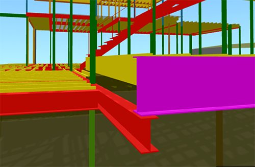
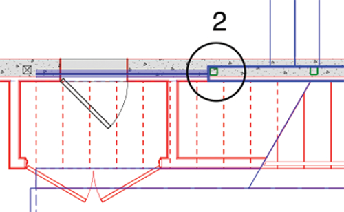
- At one corner, two floor plates come together, one higher than the other. Image: Mark English Architects
-
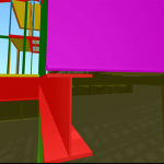
- The 3D model showed that an unintentional 3.5-inch gap between the steel beams. Image: Mark English Architects
Using the Kubity app has helped identify problems and alignments that the structural engineer may not have been able to foresee. The mobile version lets the user flip the model and zoom in on potential areas of concern. In one spot, a purple beam for a higher floor plate didn’t come down all the way to meet the beam for a lower floor plate.
There was a gap of just a few inches between the beams, when they should be touching. The floors were actually about one and a half feet apart, with a short set of stairs between them. The beams needed to be touching, for stability. The architect requested a wider beam in that spot, in order to ensure that the steel framing members matched as intended.
The digital models, together with Kubity, provided a set of tools that were easily transferable from one consultant to another, or even to the owner. The model could be spun around to see different aspects of the building, or to troubleshoot some parts of the design that are not coming together as they should.
The use of 3D visualization tools can help to forestall construction difficulties later on. By digitally constructing the building’s skeleton, especially when there is a lot of steel involved, the architect can assist with future steel shop drawings and explore questions of how things may come together in the field. Thus, creating a virtual model of the building up front, can help in all sorts of ways during the actual build.
Communicating on the Drawing
I suggested that thinking holistically would probably take longer. It’s more streamlined for the engineers to stick to what they know best – calculations and safety margins. And, in some spots, there might be issues that the engineer couldn’t have anticipated. One such area in this project was the lower right corner, where the ground dropped away sharply. The structural engineer had called for a footing that extended out past the house, which wouldn’t work on that terrain.
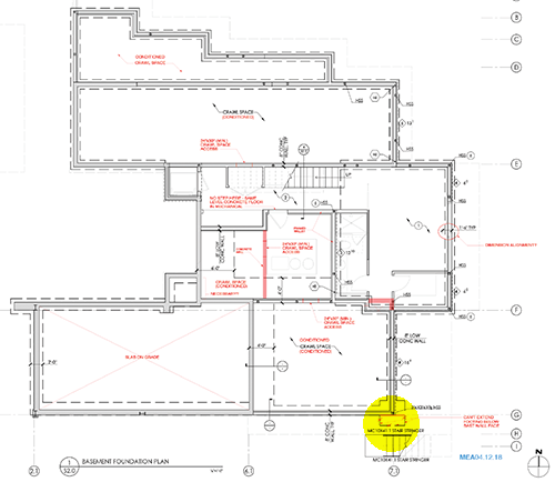
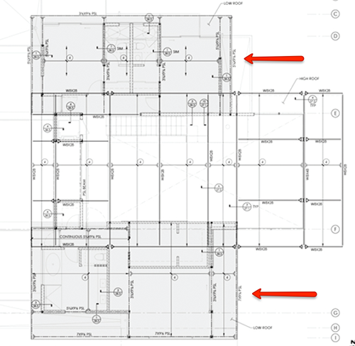
Red items on this annotated architectural progress set are comments to the structural engineer. The yellow marks a corner where the ground drops away sharply. Image: Mark English Architects
-
- There’s a problem called out in the lower right corner. Image: Mark English Architects
-
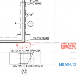
- The structural engineer has called out a footing that extends out beyond the edge of the building, which is on the edge of a cliff. Image: Mark English Architects
-

- The written comment explains the markup on the drawing. Image: Mark English Architects
Another drawing sheet from the same progress set showed the upper floor and lower roof, including a garage. The garage structural plans called for three pieces of steel, which might not be necessary given the garage’s actual size. Plus, wood could be cut onsite without the need for special steel-cutting equipment.
This small garage didn’t need three pieces of structural steel. Image: Mark English Architects
A Few Inches
The dimensions of the framing materials can have a big impact on the building’s final appearance. Even a few inches can make a big difference. The architect wants to keep profiles small. A beam that’s too thick could force the builder to create additional bumps in the ceiling in order to accommodate that thickness. That’s bad for aesthetics.
Another area on the same drawing sheet shows where the structural engineer had called out a W18X steel I-beam. The architect wanted to make that beam a W10 – slightly smaller – and add a post. Would that work?

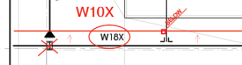
Could this roof beam be reduced from a W18X steel beam to a smaller size? Image: Mark English Architects
Different members of a design team come to the same project thinking differently about various aspects of the design. The architect is thinking about the plans: integrating the structural system into the overall design, and about finishes and aesthetics. The structural engineer is thinking about efficiency and safety factors. Having access to easily visualized models includes 3D hand sketches as well. A cross-functional design team can communicate using various types of drawings.
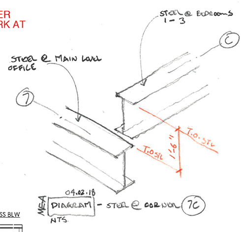
A hand sketch using trace paper over a 3D axis illustrates an area where two beams need to meet. Image: Mark English Architects
Beam Tilt
Next, the architect took the engineers steel profiles, put them into a drawing section, and reviewed the resulting exploration with the engineer. The question was: Is the beam orientation structurally sound? Some of the beams have a tilt in order to follow the roof profile. If any of those tilted beams sat over a support column, that detail might need adjustment.
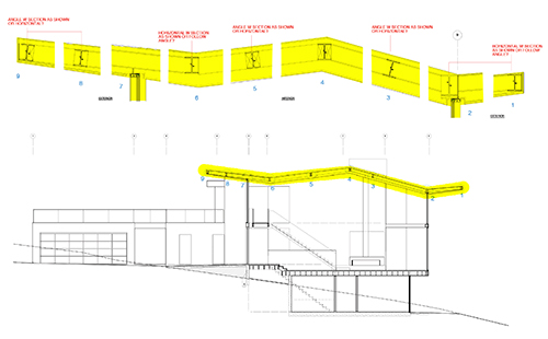
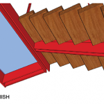
The roof profile contains structural steel beams that might be tilted to follow the roof profile. Image: Mark English Architects
-
- This architect section detail shows the engineer’s steel beams as they would be tilted to follow the roof profile. Image: Mark English Architects
-
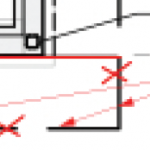
- This shows a spot where the steel protrudes into the roof ply. Image: Mark English Architects
-
- At the junction between the exterior deck and the interior, the top surface of the floors should align. Image: Mark English Architects
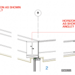
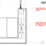
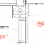
Column Placement
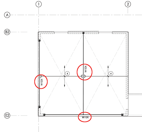
Another drawing showed a top-down view of a wall thickness, with different wall protrusions at each story. The intention was to see if there were any unintended consequences of placing structural beams a few inches over one way or another.
Top-down view of a wall that is multiple stories tall. The red is the basement, blue is the main floor. Image: Mark English Architects
In one corner of that same drawing, a gray square depicted a concrete wall, with a green square inside of that. That green square represented a steel column, located over a concrete wall.
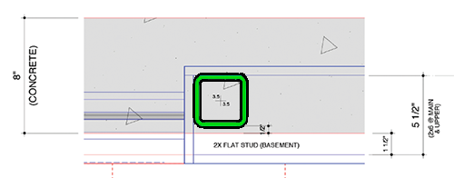
Top-down view showing steel column placement over a concrete wall. Image: Mark English Architects
If the column were to be centered inside the concrete square, it would push out the wall finishes on the upper stories. The architect wanted to locate the column 3.5 inches closer to the edge of the wall. The drawing also served as instructions to the builder on where to locate that steel column.
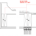
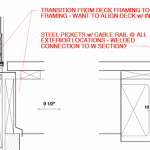
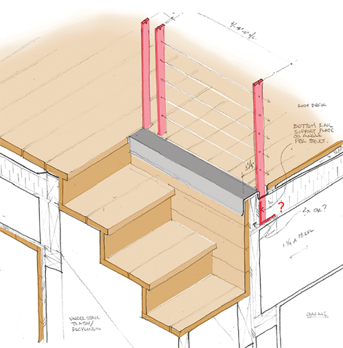
Interior Stair Assembly
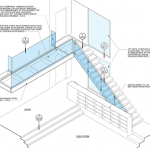
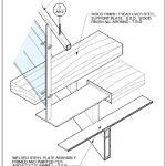
Sketches on an axonometric grid can be tool for envisioning and working out how different parts come together. In one drawing showing the top of an interior stair, the engineer had a W10X steel I-beam. The architect wanted a welded plate assembly, in an H shape (shown in the sketch as the red piece).
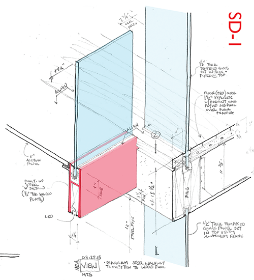
Welded steel plate at top of stair. Image: Mark English Architects
The next sketch added the stair as a cutaway assembly. The architect had to work out how the interior stair would fit in. The stair treads needed to wrap around the steel, as shown in the cutaway portion of another drawing in the same series. This drawing also showed how the top surface of the topmost stair tread and two types of floor surfaces all aligned horizontally, with vertical glass sheets that would serve as the stair rails inserted into a special shoe, which was inside the H-shaped welded steel plate.
The stairs weren’t solid blocks of wood. They actually wrapped around the steel on all sides. Further explorations occurred in Sketchup renderings.
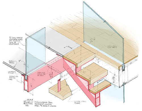
The stair meets up with the welded plate assembly. Image: Mark English Architects
-
- Stair cladding wraps around the steel frame. Image: Mark English Architects
-
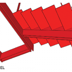
- Steel frame shown without the stair. Image: Mark English Architects
-

- LED strip lighting fits inside the steel stair frame. Image: Mark English Architects
Putting the Stair into CAD
After working out these details, the design went back into CAD. This drawing sheet served both as instructions to the builder, and for the Building Department to review for code compliance. On the right, the 3D views showed a bookshelf that was also a rail. This helped the owner to envision how the stair comes together with other design elements in the home. On the upper deck the floor was translucent, made from frosted Lucite. The rails were clear glass.
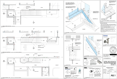
Architectural details on drawing sheet. Image: Mark English Architects
-
- The Building Department can review the details for code compliance. Image: Mark English Architects
-
- The owner can review the 3D drawing to see how the stair, the upper walkway, and a lower wood cabinet fit together. Image: Mark English Architects
-
- The stair cladding detail is worked out further. Image: Mark English Architects
Construction Assembly Notes
The CAD drawing sheets contained detailed construction assembly notes, as well as further comments and questions for the structural engineer.
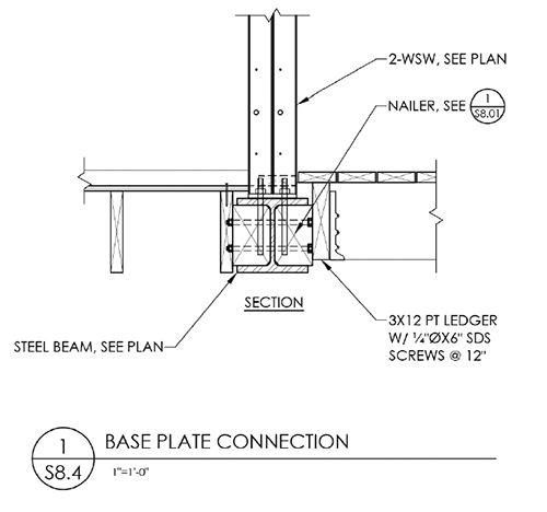
Drawing sheet explores the base plate connection and foundation footing. Image: Mark English Architects
-
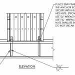
- Mechanical assembly instructions include wrench and fastener sizing. Image: Mark English Architects
-
- These assembly comments explore ways to create smooth outer surfaces. Image: Mark English Architects
-
- Small adjustments to the concrete footing. Image: Mark English Architects
Roof Deck
Another detail that required exploration through hand sketches occurred at the roof deck and exterior. The axonometric hand sketch was quicker than doing it in Sketchup. Although it couldn’t be rotated interactively, it was faster as a first step to figure out how the components came together. Using trace paper over a pre-printed grid, the architect could ensure that the drawing was proportional by counting the squares.
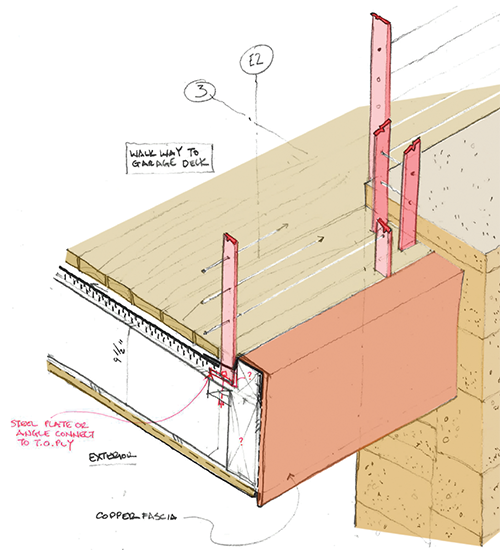
Exploratory sketch of roof deck. Image: Mark English Architects
The development of these projections, especially the hand-drawn isometrics, not only allowed for the structural details to be figured out fairly quickly, but also assisted in understanding some finish details as well – details that might otherwise be pushed down the road a bit.
The railing isometric detail drawing was developed to ask the structural engineer how the concealed railing could be attached below the deck. When doing this drawing, the only real question at the time was: How does the railing attach? However, the projection was seen as an opportunity to see how the different materials at this corner come together: wood deck to copper fascia. to stone wall to cable railing, etc.
The engineer might not care too much about other aspects of the design – only the rail attachment. However, by investing a bit more time, the architect could develop the detailing of the finished look, which could then be shown to both the owner and the builder.
What Tools Do You Need?
- It’s an iterative cycle through a number of tools to explore the same conditions using:
- Physical models
- 3D digital visualizations, like Sketchup and Kubity
- CAD drawings, in Revit
- Hand drawings, done in pencil on trace paper
- Sketches scanned and then colorized, annotated or included on CAD drawings
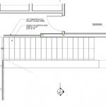
Stairs at roof deck. Image: Mark English Architects
The architect explained that these graphical projections, including hand-drawn isometrics, computer digital models (Sketchup + Kubity + VR) and physical models, could all help the architect dialogue with a structural engineer in order to get a better understanding of how the details of the building come together.
Exploration is Time Well-Spent
This process informs staff training as well. We live in a world where rapid execution is prized above all else. In this arena, the architect has to reassure new interns that it’s OK to take an extra 45 minutes, if it helps to solve problems by looking ahead. That drawing can expedite the review process, and can communicate design intent with many different parties all at once.
How do these drawings serve the project?
- The architect can review the drawing quickly and understand right away what is being proposed.
- The engineer can comprehend the problem or question at hand.
- The builder can see how it all comes together.
- The owner can see how components fit together, and how it will look after it’s built.
- The metal fabricator can use this drawing to dimension and create the components.
The process requires an open mind, a willingness to ask questions as a way of teasing out possible methods of bringing components together. “These sketches are useful to many people, and the first party is YOU. Then we can start thinking, who else needs to know this?”
A drawing can be used as a starting point to explore one question, and then allow the architect to leap forward to explore how other pieces around it come together – sometimes, just with a pencil and trace. Sometimes the simplest of technologies can be the most powerful tool of all.
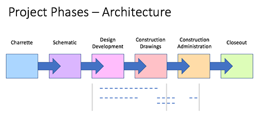
The explorations occur across the design development and construction drawing phases. Image: Mark English Architects
Most of what we’re showing here happens during the design development and later phases. Earlier, during schematic design, the architect is mainly concerned with volume, materials, and initial reviews by the Planning Department. Design development starts to look at code compliance, structural calculations, and Building Department review. Construction drawings are shop drawings. Hand sketches may also be used in the field during construction administration to solve issues that crop up while the project is being built.
When is a Drawing “Done”?
How do you know you’re not overthinking things? I wondered this because there’s obviously a point where going over and over the same ground yields less and less new information. So how do you know when it’s time to move on? How do you know when your drawing is “good enough”?
One art teacher has said, “A drawing is done when you don’t know what else to add… when you don’t know why you’re still putting the brush to the canvas.” For this architect, the drawing is done when it needs to be passed on to someone else. A hand sketch allows the architect to take a step back and see new things. Or, maybe the architect starts adding color, and begins to contemplate the drawing on a different level.
Physical Models
Physical models serve the design as well. Physical model-building is a means by which to experience the space in a different way, and is perhaps the most accessible to a client without formal design training, because we can pick up and handle the model using our hands. This practice engages more closely with our own sensory system. It is less virtualized and more tangible. By combining physical models with the 3D modeling and other types of drawings, the architect gains a better understanding and communicates that understanding more effectively to the project’s advantage.
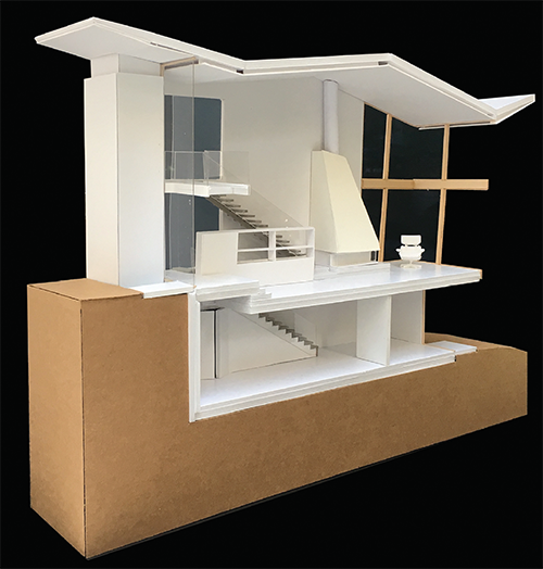
Image: Mark English Architects


Daphne Gilpin
25. Mar, 2019
Thanks for explaining that the roof contains structural steel beams which are tilted to follow the profile of the roof. I’m trying to learn more about the framework and construction of structural steel buildings. The info you shared about the uses for roofs was very informative!
Gillian Babcock
31. Mar, 2019
My brother is planning to build a warehouse and he wants to make sure that it’s structurally sturdy. It was explained here that in order to save up on steel, a structural model should be made. Furthermore, it’s recommended to hire professional contractors when planning to use structural steel.
simon
17. May, 2019
Thanks for sharing this Great article
I appreciate the valuable time you have used to share this.
Jenna Hunter
20. Jun, 2019
My uncle is thinking about getting an architect. Making sure his house is really well done would be benefited by having a professional. It was really cool to learn about structural-architectural integration.
Structere
18. Sep, 2019
Great information. Absolutely worth reading and learning. Very useful information. Thanks for this.